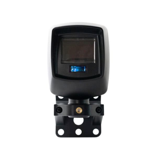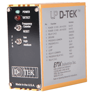
MVP D-TEK Overview
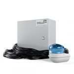
The MVP D-TEK multi-voltage vehicle detector makes it simple to manage your stock. All you need is one detector in your stock room and on your truck. This multi-voltage vehicle detector solves the problem of not knowing which voltage to take for service a call or installation. Reduce the cost of inventory by stocking only one loop detector – with the universal voltage of our MVP D-TEK.
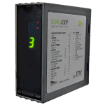
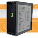
Features of Our Multi-Voltage Vehicle Detector
- Multi-voltage power 12 to 220 VAC/DC
- Operates in both fail safe and fail secure modes
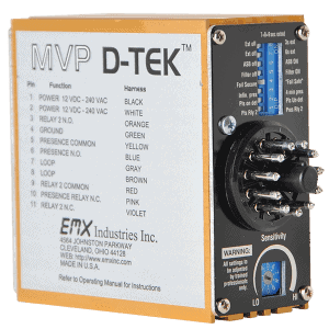
- 10 sensitivity settings
- Enhanced lightning/surge immunity
- Aluminum RF shield housing
- Built-in loop conditioner
- Loop isolation transformer
- Loop diagnostics
- Frequency counter
- Gold plated control contacts
- 2 relays (presence & pulse or presence)
MVP D-TEK Specs
| Power Supply | 12VDC to 240VAC |
| Current Consumption | 19.2mA @ 9VDC, 18.8 mA @ 12VAC/DC, 17.3 mA @ 24VAC, 9.5 mA @ 24VDC, 13.5 mA @ 115VAC 11.0 mA @ 237VAC |
| Operating Temp | -40°F to +180°F |
| Surge Protection | Zener Diode /MOV |
| Output Relays (2) | 1Amp 30 VDC |
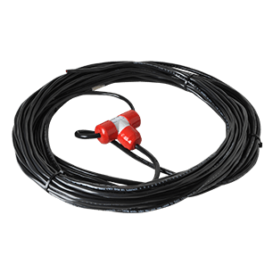
| Loop Input | Transformer isolation, lightning and transient protection (1) |
| Loop Inductance Range | 20 – 2000 uH Q-factor of 5 or higher |
| Tuning | Automatic on reset or power up |
| Tracking | Automatic for environmental changes |
| Size | Height 3.25” (83mm) Width 2.56” (40mm) Length 3.65” (90mm) |
| Housing | Extruded Anodized Aluminum |
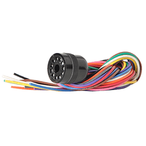
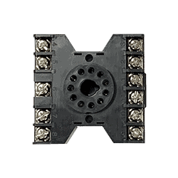
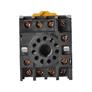
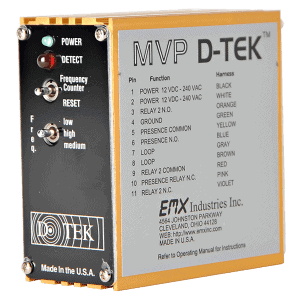
| Connector | 86CP11 11 pin male |