USVD-4X Overview
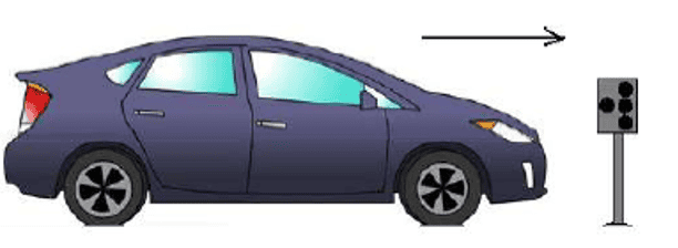
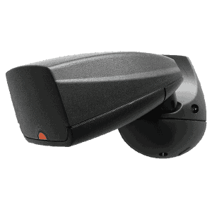
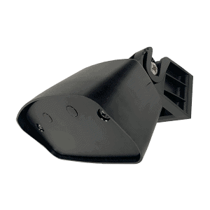
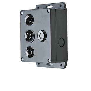
The USVD-4X drive thru vehicle detector uses Triangular Planar Array (TPA) technology to detect the presence of a vehicle. The USVD-4X ultrasonic vehicle detector handles any drive thru operation, including fast food, banking, pharmacies, car washes and parking.
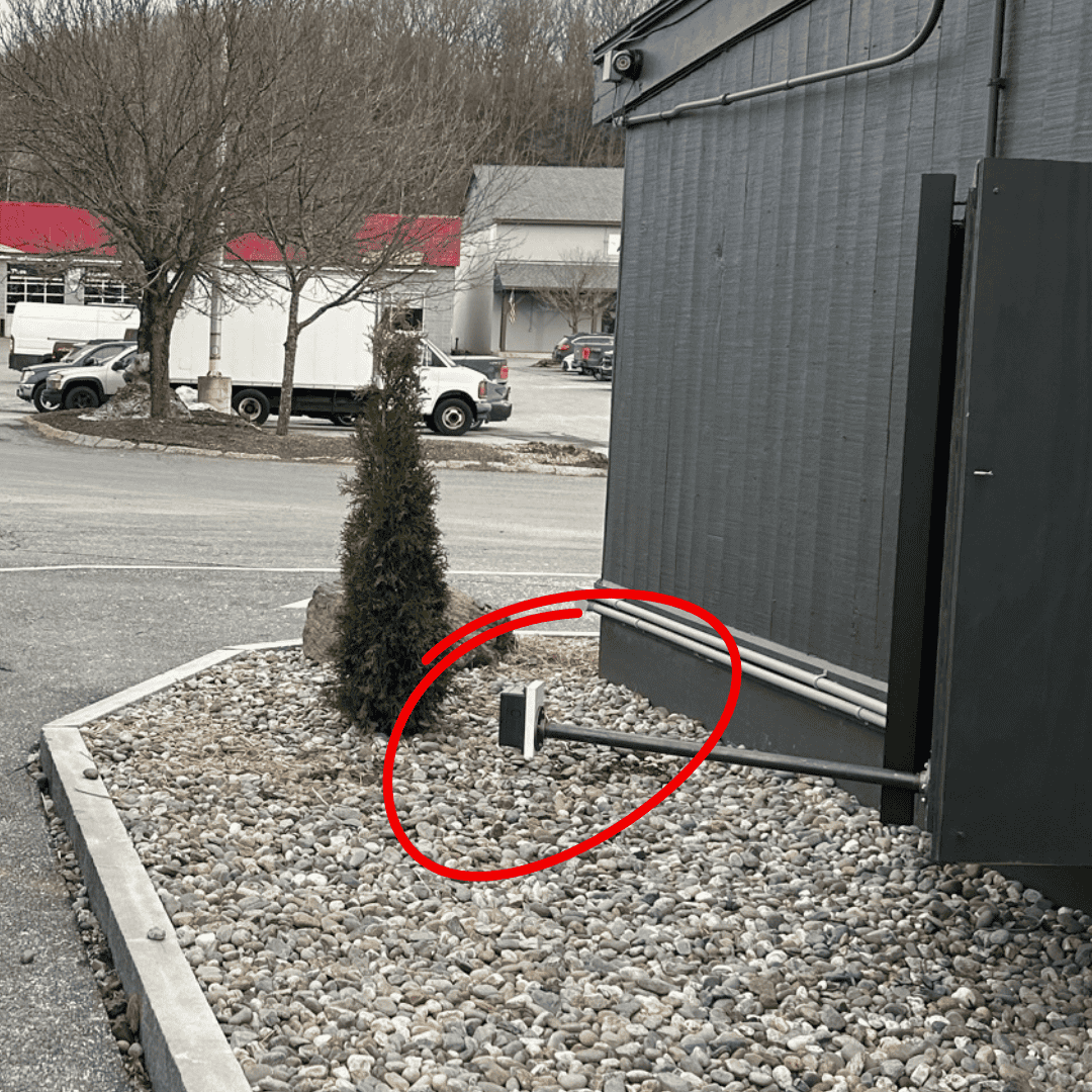
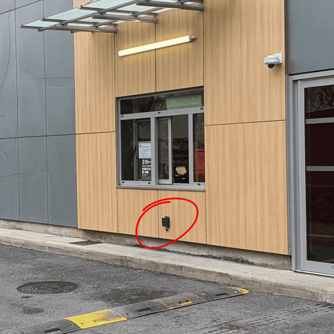
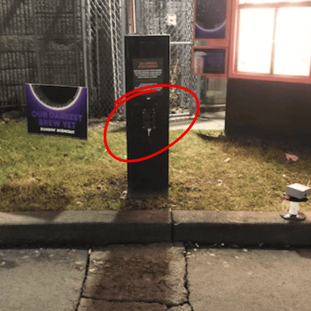
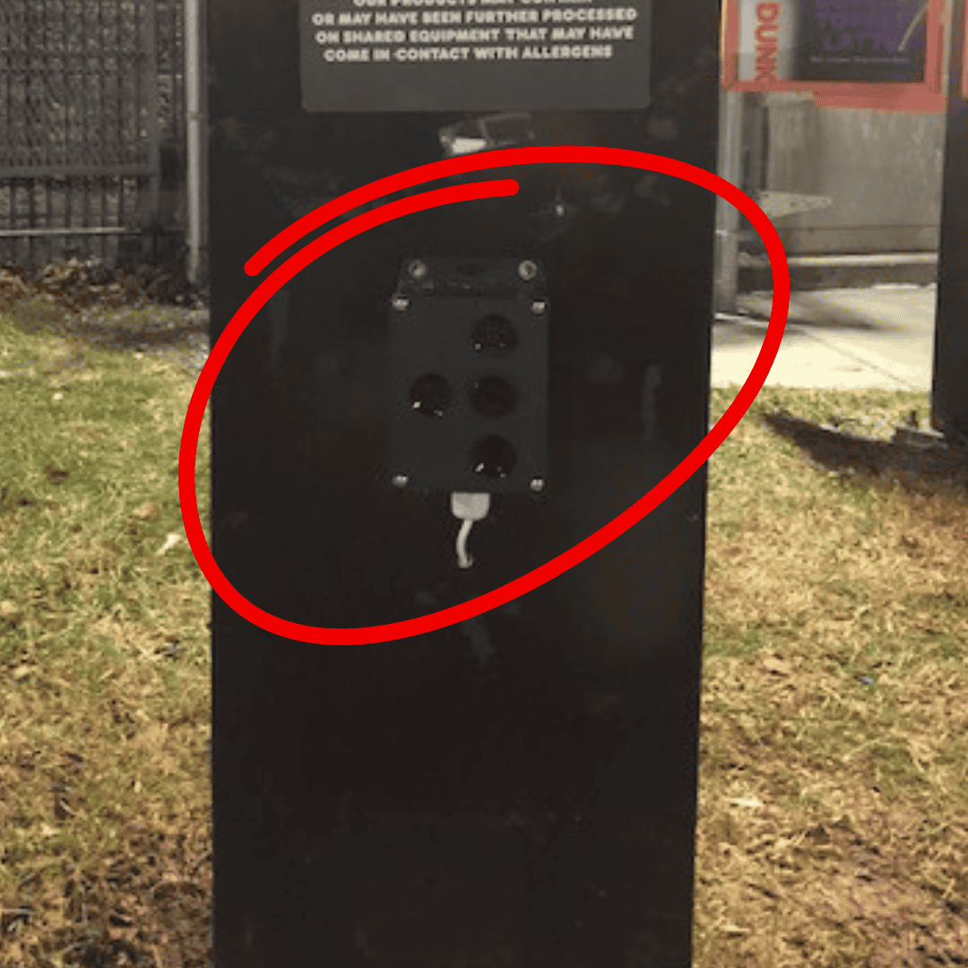
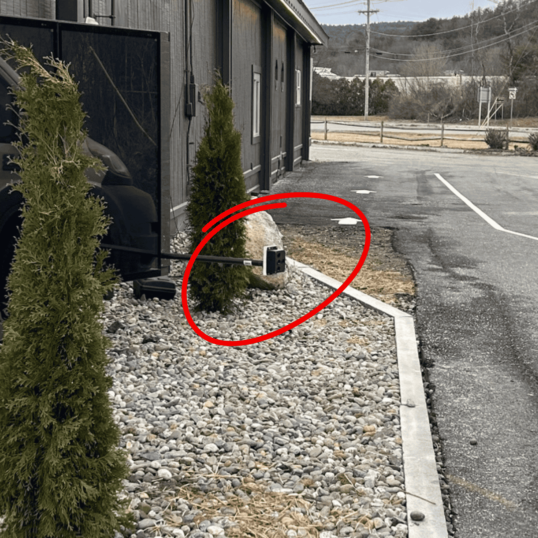
For these types of applications, the USVD-4X is much less expensive than traditional vehicle loop detectors, which require the installation of a loop in pavement. The USVD-4X ultrasonic vehicle detector is simply mounted on a post or order box, and aimed at the location where a vehicle would pass to initiate a transaction. No set-up or adjustments required.
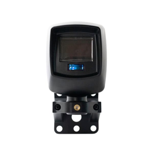
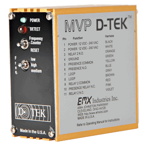
The USVD-4X requires 12-24VDC/VAC, and provides a form “C” set or relay contacts indicating vehicle presence. Utilizing TPA technology, the detection head consists of 4 ultrasonic transducers that connect to the internal microprocessor-based control board. The detection head “scans” the expected location for a vehicle and activates its output upon detection of a vehicle.
Features of Our Ultrasonic Vehicle Detector
- Triangular Planar Array Technology
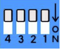
- Aux. relay, settings for pulse on ENTRY, EXIT or BOTH
- Output delay option for 1, 2 and 4 seconds
- Operating range: 1ft. – 5ft.
- Response time: 2.0 seconds
- Supply Voltage12…24 VDC/VAC
- Relay output configuration: 2 SPDT (form C)
- CE compliant
USVD-4X Specs
| Sensing elements | 4 ultrasonic in TPA configuration |
| Operating range | 1ft. – 5ft. |
| Response time | 2.0 seconds |
| Relay output configuration | 2 SPDT (form C) |
| Relay contact rating | 1A @ 24VDC |
| Power indicator/no vehicle | Green LED |
| Object in range | Flashing Green LED on each input, continuous LED on DETECT |
| Supply voltage | 12…24 VDC/VAC |
| Operating current | 60mA |
| Operating temperature | -40°C…+85°C (-40°F…+182°F) |
| Dimensions | 5.7”(145mm) x 3.6”(90mm) x 2.3”(57mm) |
| Weight | 0.6 lbs. (275g) |
| Housing | ABS NEMA 4X |
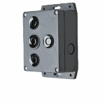
| Connection | 10 position terminal block |
| Mechanical protection | NEMA 4X |