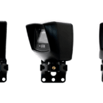
About Our NIR-50 Retroreflective Photoeye
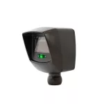
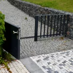
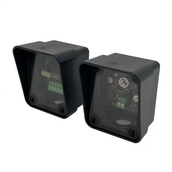
The NIR-50 is an extended range, retroreflective photoeye that provides entrapment protection for overhead doors, gates and barriers. This retroreflective photoeye sensor offers flexible voltages, a compact design and LED indicators, making the NIR-50 an easy-to-install system.
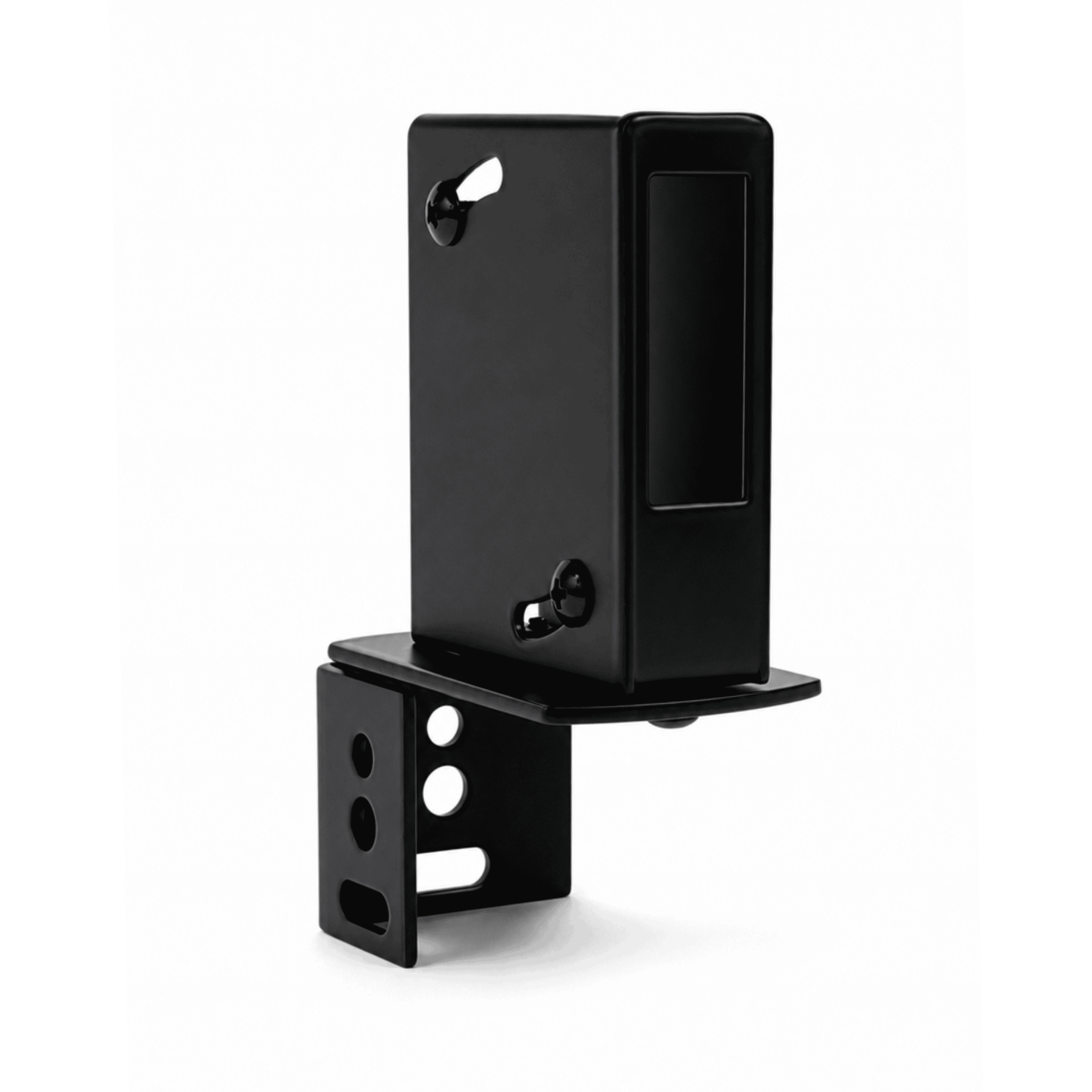
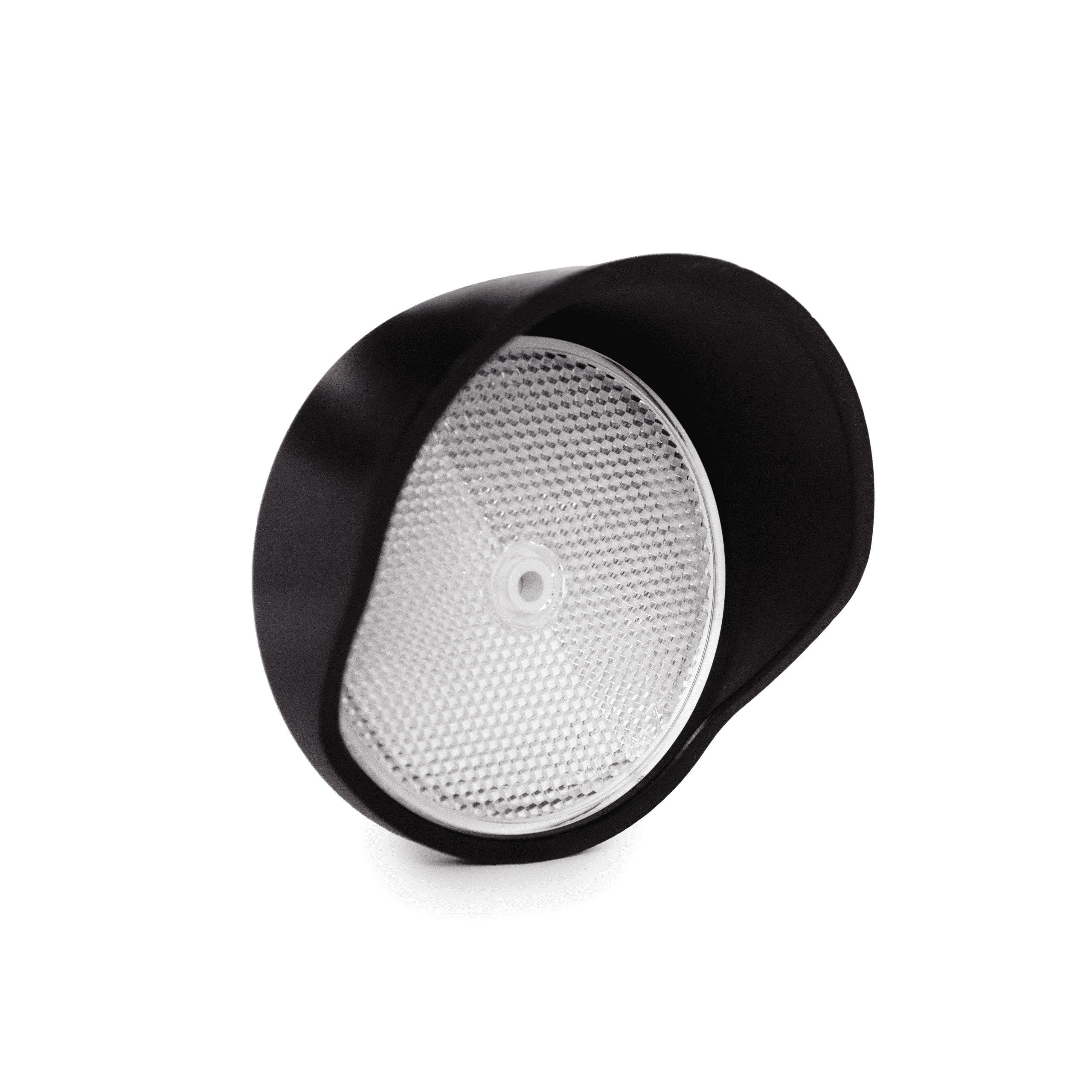
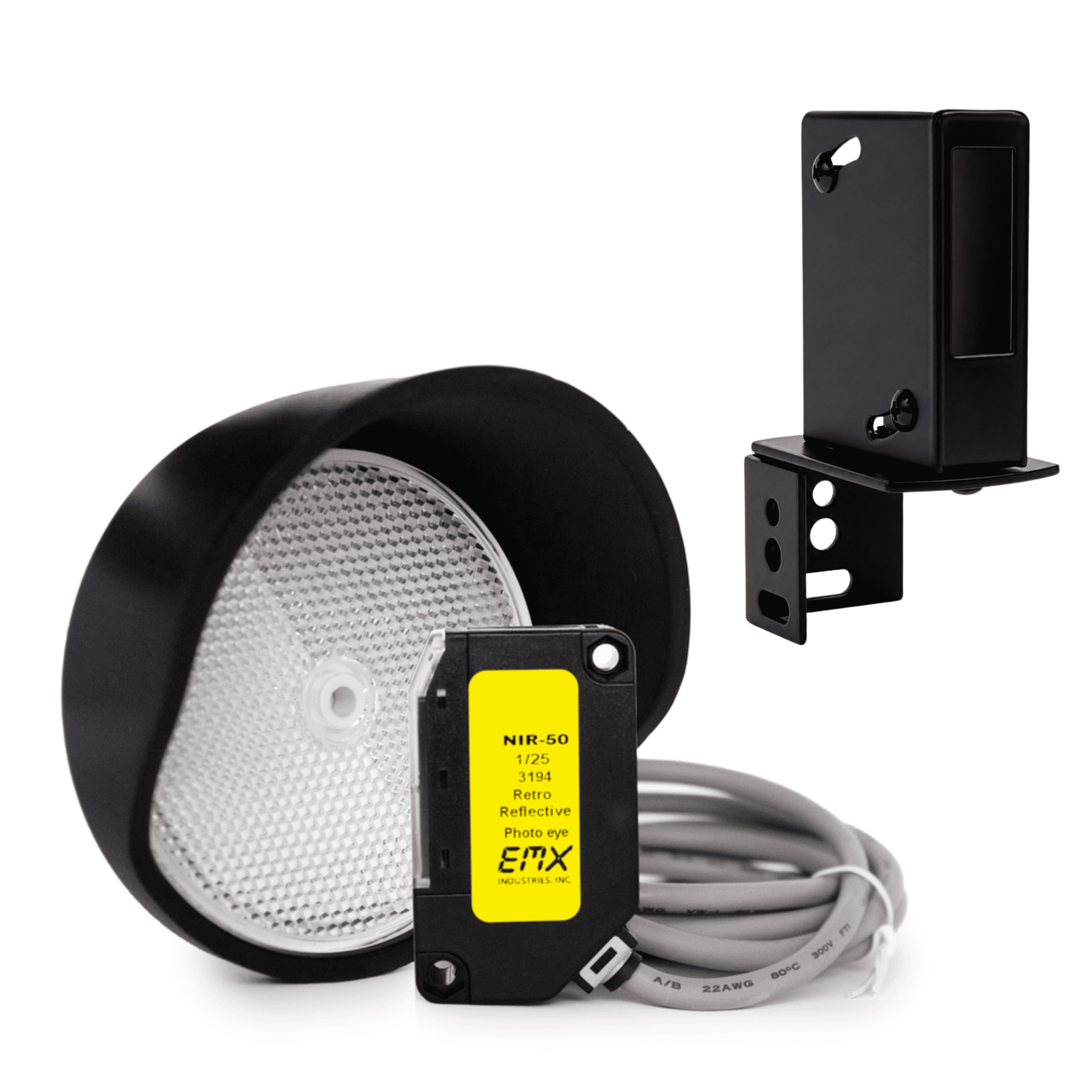
The NIR-50 kit includes: photoeye with hood, reflector with hood, and mounting bracket with hardware.
For gate or door operators that require a monitored safety device, see our UL325 photoeyes. The NIR-50 is not UL compliant.
Features
Flexible voltage: 12 – 240 VDC, 24 – 240 VAC
Watertight package for reliable outdoor installation
Operating range: 50 feet
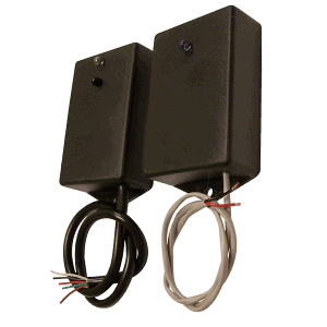
Lead wire: 6 feet
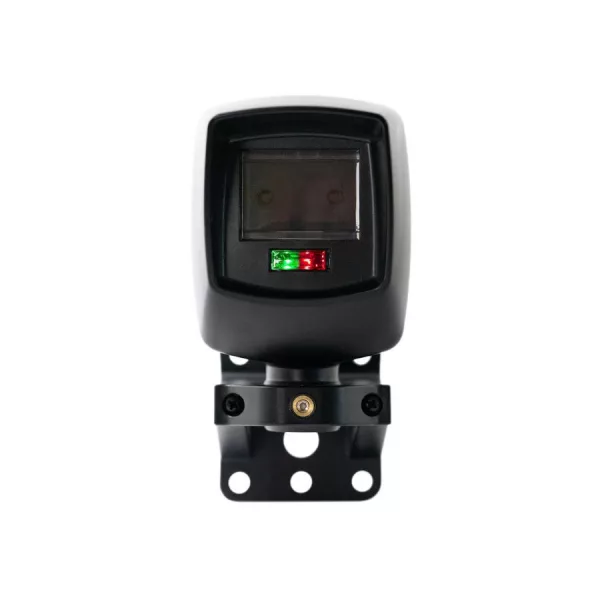
2 LED indicators
Sensitivity adjustment
Compact size: 2.5″ high, 1.5″ deep, 0.75″ wide