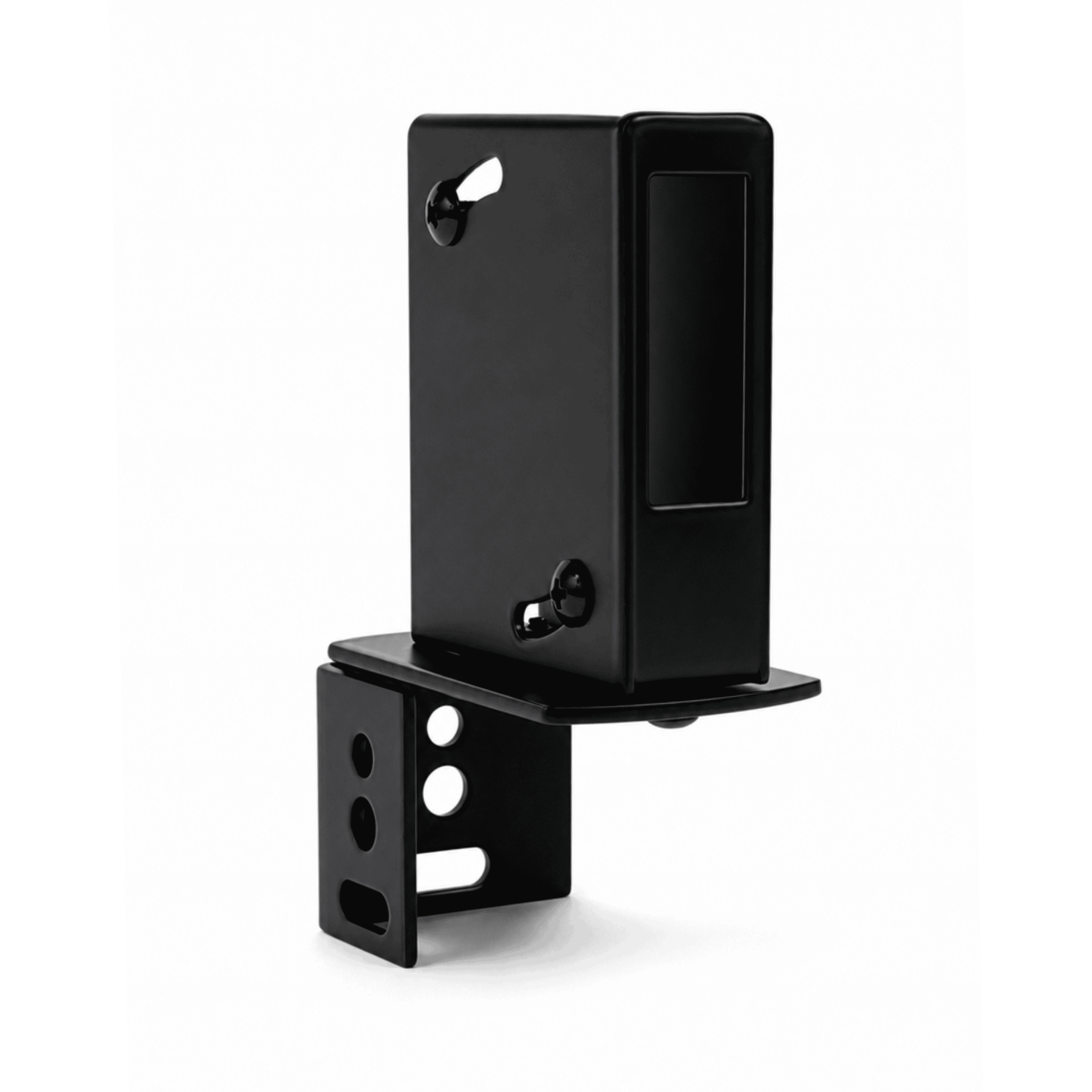
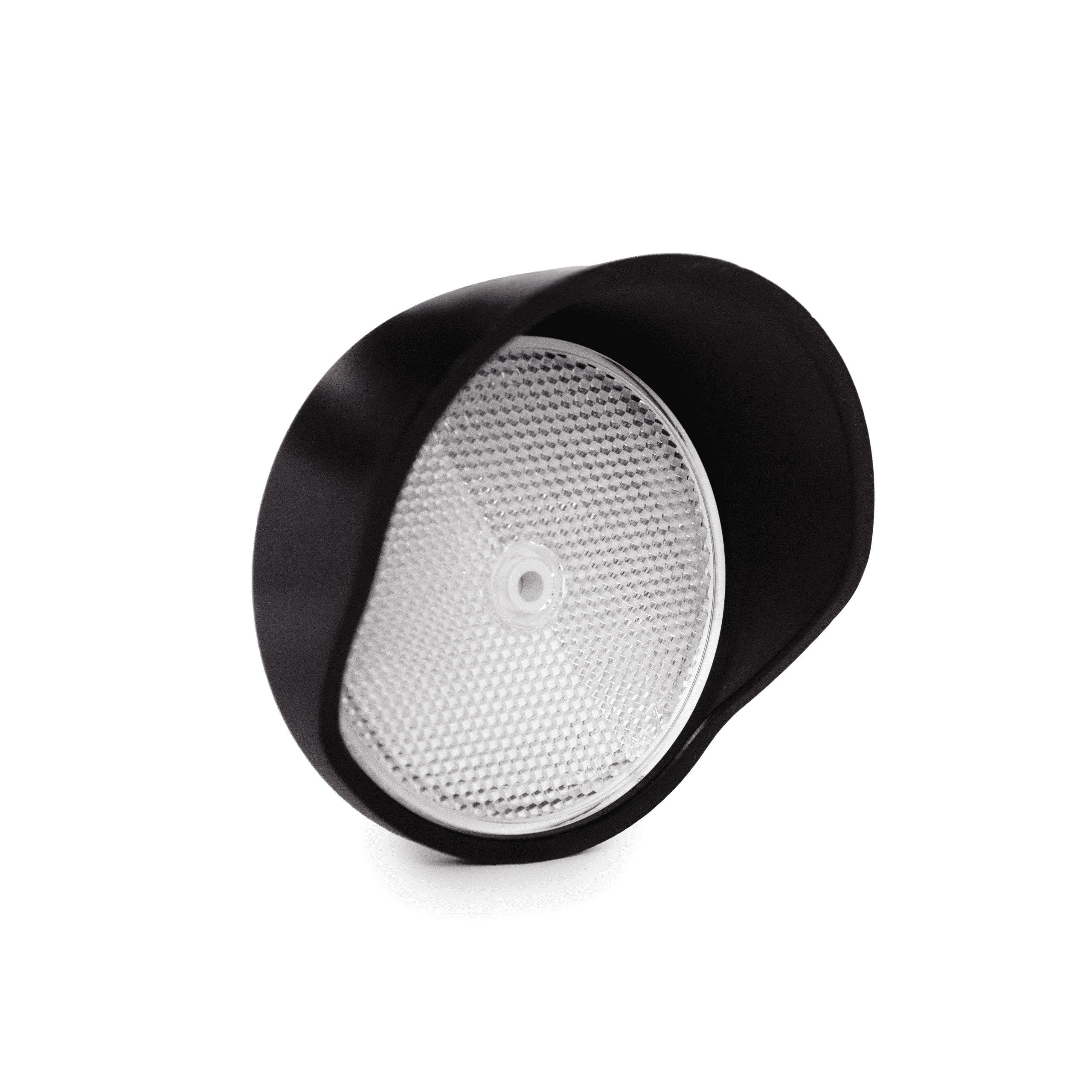
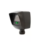
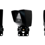
NIR-50-325

UL325 Retroreflective Photoeye Kit

  • Kit includes photoeye with hood, reflector with hood, and mounting bracket
  • Retroreflective configuration
  • NC and 10K monitoring
  • 50 ft. operating range
  • Sensitivity adjustment
  • Wide range operating voltage
  • IP66 enclosure

PART NUMBERS:

  • EMX-5255-K: NIR-50-325 – KIT W/SENSOR & REFLECTOR HOOD
  • EMX-5255-2: NIR-50-325 – RETROREFLECTIVE PHOTOEYE ONLY

NIR-50-325 Overview

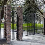
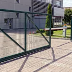
The NIR-50-325 is an extended range, retroreflective photoeye sensor providing entrapment protection for overhead doors, gates and barriers. The NIR-50-325 is UL325-2018 compliant and features an internal 10K resistor for monitored operation. Its flexible voltages, compact design and LED indicators make this photoeye easy to install.

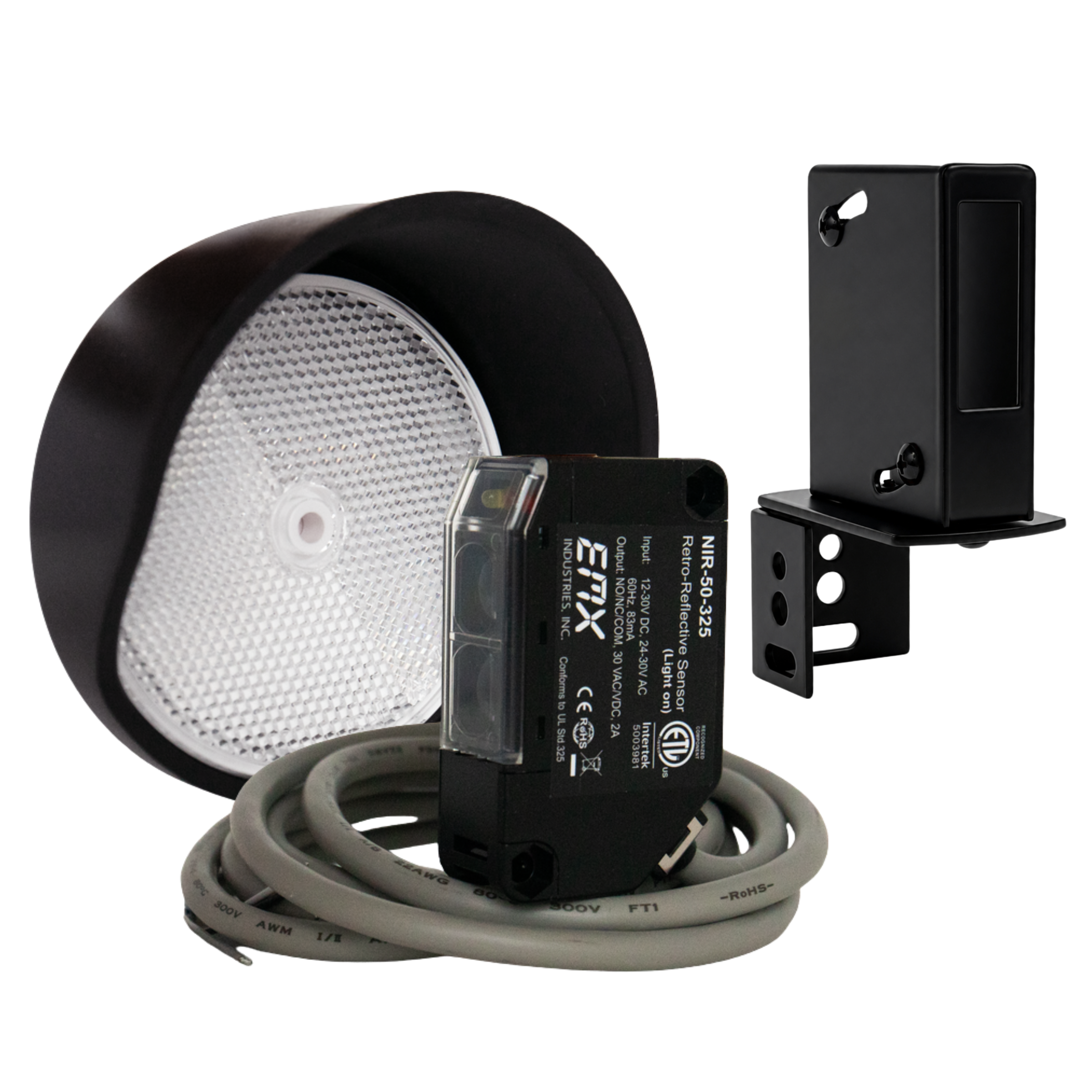
The NIR-50-325 kit includes: photoeye with hood, reflector with hood, and mounting bracket with hardware.

This retroreflective photoeye is not compatible with operators that use NO and COM (non-10K) monitoring methods.

Features

  • UL325-2018 complaint
  • Flexible voltage: 12-30 VDC, 24-30 VAC
  • Watertight package for reliable outdoor installation
  • Operating range: 50 feet
  • Lead wire: 6 feet
  • 2 LED indicators
  • Sensitivity adjustment
  • Compact size: 2.5″ high, 1.5″ deep, 0.75″ wide

Specs

Operating range 0.5ft (0.1m) …50ft (15.2m)
Sensitivity adjustment Potentiometer
Signal stability indicator Yellow LED
Alignment indicator Red LED
Relay output Form C contacts (NO, COM, NC), 30VAC/VDC, 2A
Resistive termination 10k Ohm (internal)
Response time 10ms
Power 12…30VDC, 24…30VAC @ 60 Hz
Current draw 83mA
Operating temperature -4°…131°F (-20°…55°C)
Environmental protection IP 66 IEC
Dimensions (L x W x H) 1.3” (33mm) x 0.8” (21mm) x 2.6” (66mm)
Weight 0.2 lbs (91g)
Connections 5 wires, 6.5’ (2m) cable
Certifications CE, UL325-2018

NIR-HD
Black powder coated steel protective hood

REFLECTOR-O
White plastic reflector
3″ diameter

REFLECTOR-O-HD
Gray plastic protective hood for reflector

NIR-BR
Black powder coated steel mounting bracket

Spec Sheet

Manual

Spanish Manual

What is the difference between the NIR, NIR-50, and NIR-50-325?

NIR and NIR-50: The NIR and NIR-50 can be used in all non-monitored applications. This is particularly relevant for older gate operators made before 2016. The NIR has a range of 30 feet and has standard NC and NO contacts. The NIR-50 has a range of 50 feet and has a standard NC and NO contacts.

NIR-50-325: The NIR-50-325 has a range of 50 feet and can be used in normally closed or 10k resistive monitored applications with monitored UL-325 gate and overhead door operators. It cannot be used with a normally open (NO) connection to a non-monitored operator because it has a 10k resistor internally connected to the normally open wire.

How do I wire this photoeye to my operator?

Wiring Instructions: Follow the below table to identify the correct signal wires for your gate operator. Check with your gate operator manual to make sure you are using the correct monitoring method associated with the diagram below. The NIR-50-325 cannot communicate across the Gray (NO) wire with a non-monitored operator. The normally open connection can only be used with 10k monitored UL325 operators. Updated as of 3/4/2025

Gate Operator Signal Wires Monitoring Method
Apollo/Nice Gray (NO), White (COM) 10K Resistive
All-O-Matic Black (NC), White (COM) Normally Closed
AutoGate Gray (NO), White (COM) 10k Resistive
DoorKing Gray (NO), White (COM) 10k Resistive
FAAC Black (NC), White (COM) Normally Closed*
HySecurity Black (NC)**, White (COM) Normally Closed
LiftMaster Gray (NO), White (COM) 10k Resistive
Linear (Apex) Gray (NO), White (COM) 10k Resistive
Max Controls Black/Gray, White (COM) NC or 10k
US Automatic Gray (NO), White (COM) 10k Resistive
Viking Gray (NO), White (COM) 10k Resistive

* Some FAAC gate operators require only the transmitter to be power cycled. The NIR-50-325 does not have the ability to do this and is not compatible with those operators.

** HySecurity gate operators using the SmartCNX Controller require 10k Resistive (Gray NO wire, White COM wire) for this device

How do I configure my photoeye to be non-monitored?

Non-Monitored Setup: This photoeye can connect to a non-monitored operator that can take a normally closed (NC) connection by using the black wire (NC) and white wire (COM). This photoeye cannot be used with a normally open (NO) connection to a non-monitored operator because it has a 10k resistor internally connected to the normally open wire.

Why won’t my reflector align?

Device Alignment: Try holding the reflector close to the photoeye, but still at least 6 inches away, and see if the lights on the front come on – indicating proper alignment. If the yellow light is not on solid, move the reflector until it is on solid, indicating optimal reflector position and alignment.

Sensitivity Adjustment: Set sensitivity to maximum by turning it clockwise until it stops. When the device aligns, turn the sensitivity back down as much as possible while the red and yellow lights are still on solid.


NIR-50-325 sensitivity adjustment

My photoeye is hooked up to a power source but the red and yellow lights on the front of my photoeye are off.

This device may be powered on, but the lights will not come on until it is aligned with the reflector.

Device LEDs: Until the NIR-50-325 is aligned with the reflector, the front red and yellow lights on the device will remain off. Try aligning the reflector with the photoeye at least 6 inches apart from each other and see if the lights on the front come on.

Aligning Reflector: Hold and align the reflector at least 5 feet away from the photoeye and slowly back up to where the reflector will be mounted. Move the reflector left, right, up, and down to find the detection pattern. Adjust the photo eye aim and mount the reflector as close to the center of the pattern as possible to ensure the strongest signal.

Sensitivity Adjustment: Set sensitivity to maximum by turning sensitivity dial clockwise until it stops. The infrared beam is not a line, it’s a cone. When at the edge of the cone, the red light will come on but the yellow light will stay off until it is near the center where the signal is strongest. Turn the sensitivity back down as much as possible while the red and yellow lights are still on solid.

Check Power: Using a multimeter, check the power source connected to the NIR-50-325 across the brown and blue wires. Voltage should read between 12-30 VDC or 24-30 VAC.


NIR-50-325 power check

Why do the red and yellow lights on the front of my photoeye go off when I break the beam, but my gate doesn’t respond?

There may be a problem with the relay or the wrong signal wires for this operator may be in use.

Correct Signal Wires: Make sure that the device is wired for the correct monitoring method for your gate operator. Required monitoring method can be found in your operator manual. Additionally, monitoring methods for various operators can be found in the above table under question, “How do I wire this device to my operator?”

NIR-50-325 Relay

  1. While the NIR-50-325 has power and is aligned with the reflector, indicated by red and yellow lights both on, disconnect the output wires (Black, White, and Gray) from the operator.
  2. Set digital multimeter to check for resistance in ohms. Connect one meter lead to white (COM) and the other meter lead to gray (NO).
  3. The meter should read about 10k ohms. Break the IR beam between the photoeye and reflector. Verify the photoeye’s red and yellow lights turn off when breaking the beam and the meter reads less than 10 ohms. If the meter is still showing about 10k ohms resistance, then the relay is defective.

Why does my photoeye not detect an obstruction even though one is present?

Unwanted Reflections: Any highly reflective surfaces may reflect the signal back to the photoeye and show an alignment.

High Sensitivity: Try turning the sensitivity down counterclockwise by one or two levels until the photoeye’s red and yellow lights both are off while an obstruction is present.


NIR-50-325 sensitivity adjustment for obstruction detection

When my reflector or sensor is wet from rain or dew my photoeye or there is heavy rain, snow or fog, the photoeye acts like there is an obstruction blocking the beam when nothing is there.

Protective Hood: EMX has a photoeye hood (NIR-HD) and reflector hood that can be purchased to keep rain off the photoeye and reflector.

Poor alignment: It is possible that the photo eye and reflector are on the edge of being aligned and any interference such as heavy rain, snow or fog could be blocking the beam. A properly aligned photo eye should work well in most weather conditions. Check to see if the reflector is properly aligned with the photoeye, by disconnecting the reflector from its mounting location and move it up, down, left and right to confirm if the original mounting location is in the center of the infrared cone being projected from the sensor. If it is not, adjust the photo eye and retest the alignment and confirm the reflector is mounted in the center of the infrared cone. This ensures the strongest signal.

Reflector Maintenance: Apply a hydrophobic solution to the reflector. Like Rain-X: Plastic or a similar solution.

Why does my NIR-50-325 have the red light on and yellow light off?

The NIR-50-325 is receiving poor signal back from the reflector.

Adjust Alignment: The reflector may not be at the center of the infrared cone coming from the transmitter. Hold and align the reflector at least 5 feet away from the photoeye and slowly back up to where the reflector will be mounted. Move the reflector left, right, up, and down to find the detection pattern. Mount the reflector as close to the center of the pattern as possible to ensure the strongest signal.

Low Sensitivity: The sensitivity may be too low. Increase the sensitivity by turning the dial clockwise until the red and yellow light both go on solid.


NIR-50-325 alignment adjustment

You may also like...

Have Any Questions ?

Have questions or need pricing on one of our products?