IRB-RET2 RetroReflective Photoeye

Universal UL325 Retroreflective Photoeye Kit

  • Universal UL325 Retroreflective Photoeye Kit
  • Compact design
  • Easy LED alignment
  • Easy-to-Adjust Ball & Socket Bracket
  • Rugged enclosure
  • Integrated sensor hood, improved reflector hood, and ball & socket bracket
  • Selectable Stealth Mode for security
  • 1/2 inch conduit connection
  • 60 ft. operating range
  • Six monitoring interfaces
  • Effortless installation and setup

PART NUMBERS:

  • EMX-1122-1: IRB-RET2 KIT W/REFLECTOR HOOD

EMX IRB-RET2 OVERVIEW

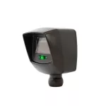
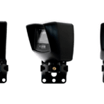
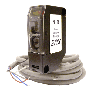
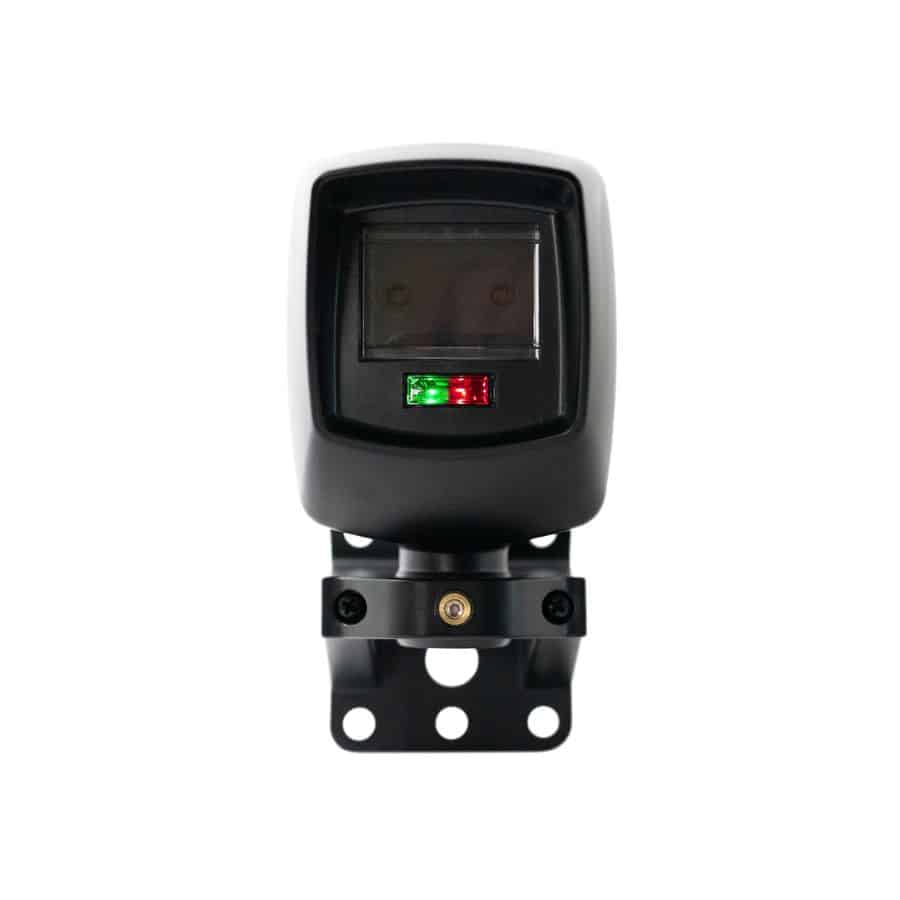
Introducing the all-new IRB-RET2 Retro-Reflective Photoeye from EMX Industries – the latest innovation in access control. This weather-proof photoeye solution delivers advanced entrapment protection for automatic gates and doors.

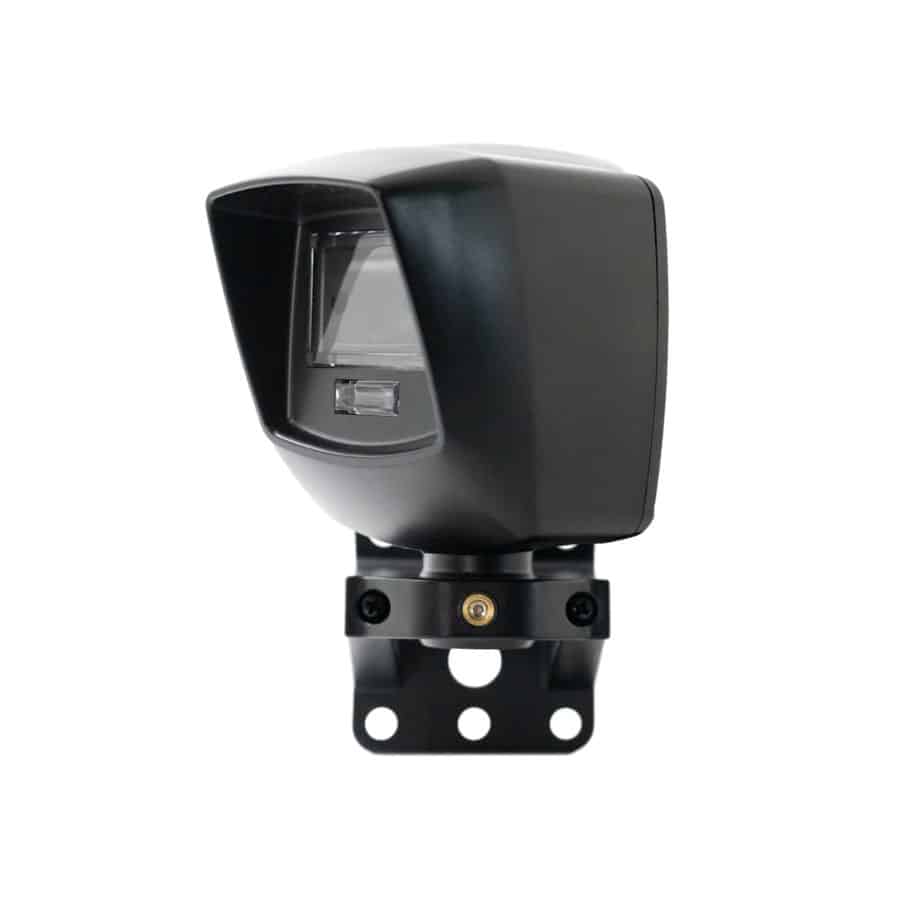
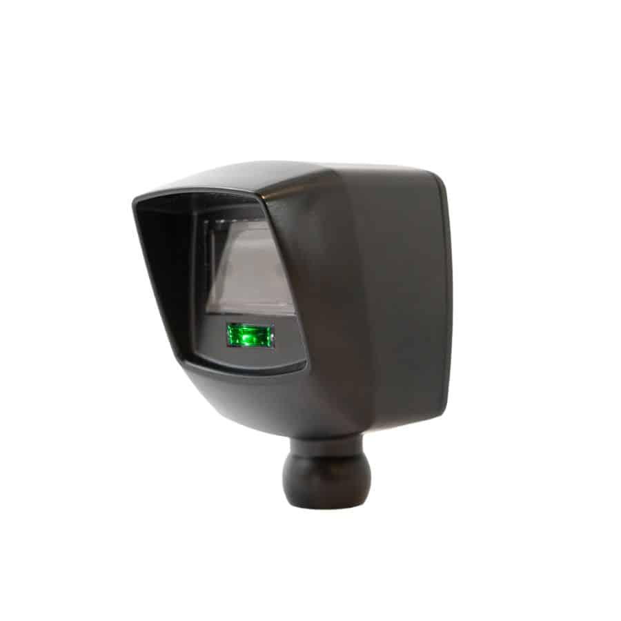
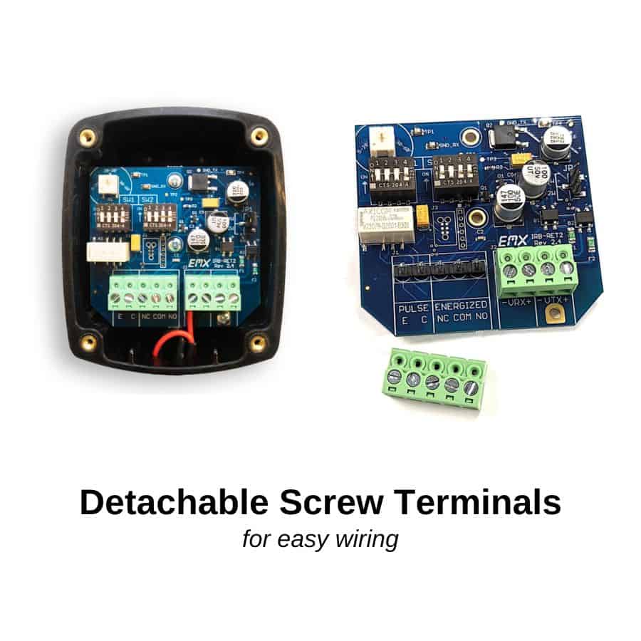
The sleek and compact design of this photoeye, coupled with an easy alignment LED, simplifies your installation process. Its rugged enclosure makes it perfect for both indoor and outdoor use, while its compliance with UL325-2018 ensures both safety and performance.

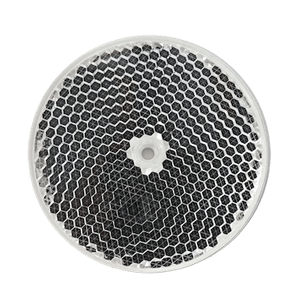
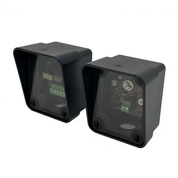
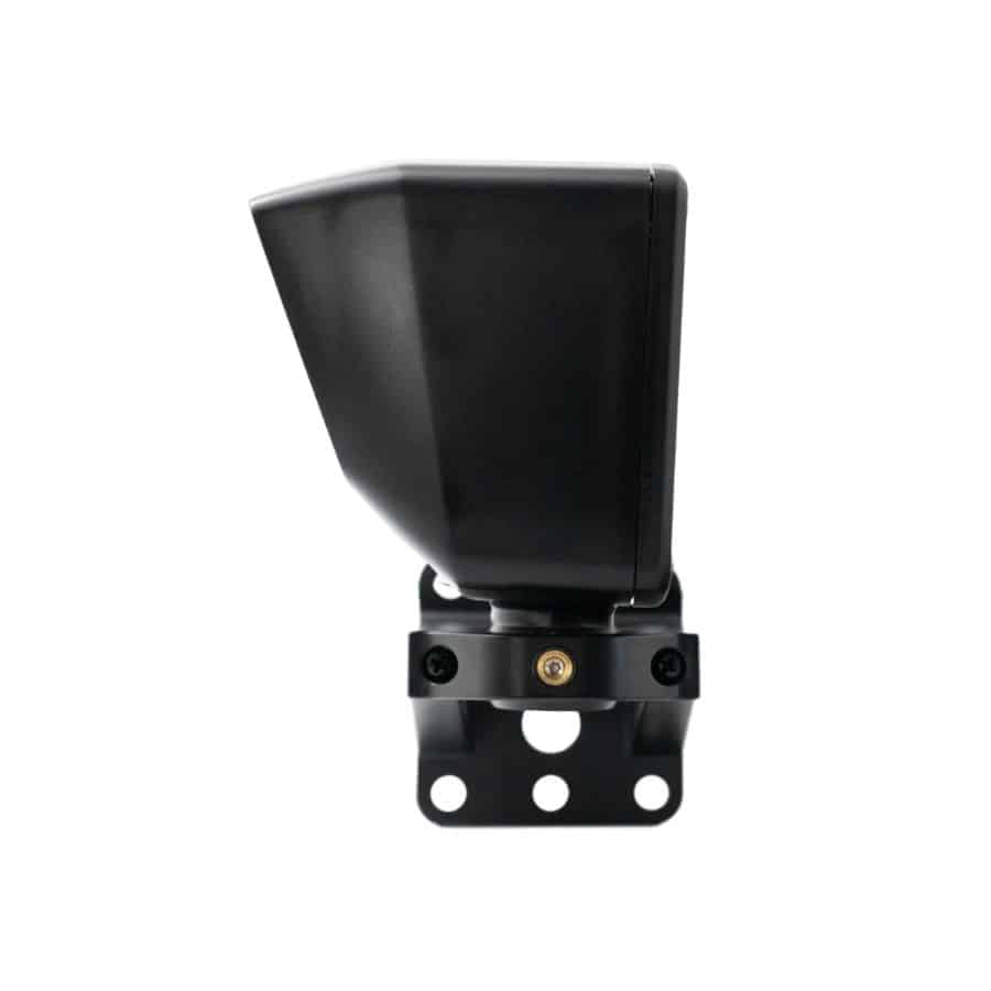
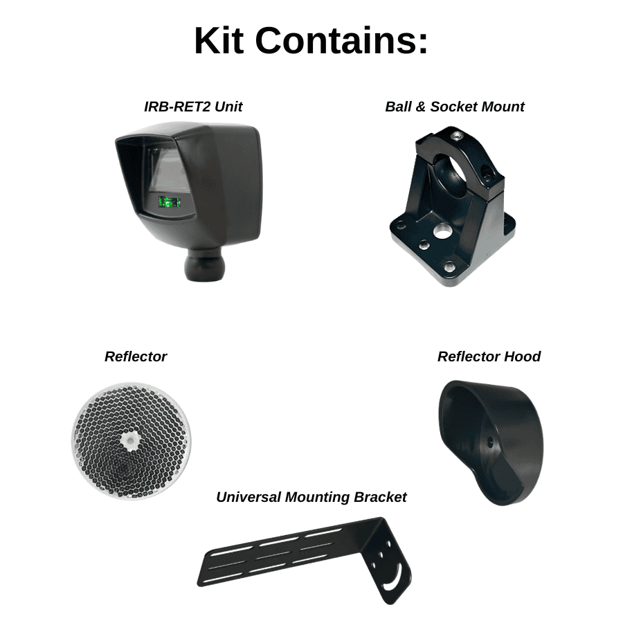
The IRB-RET2 utilizes a universal design that seamlessly integrates with a wide variety of monitored operators and non-monitored legacy products, making it incredibly versatile. And with the included ball and socket bracket, you can mount and align your photoeye with ease.

For added security and deterrence against vandalism, the IRB-RET2 features a Selectable Stealth Mode. This discreet feature turns your sensors LEDs OFF after 30 seconds of no obstructions for a discrete installation.

Investing in the Retro-Reflective Photoeye means enhanced security, increased functionality, and peace of mind for automatic gates and doors. Discover the benefits for yourself and upgrade to the latest from EMX Industries now.


Features of the IRB-RET2 Photoeye

  • Type B1, non-contact sensor
  • UL 325-2018 compliant
  • Operating range up to 60 ft. (18.3 m)
  • Rugged enclosure
  • Sensitivity adjustment: potentiometer
  • Easy Alignment LED
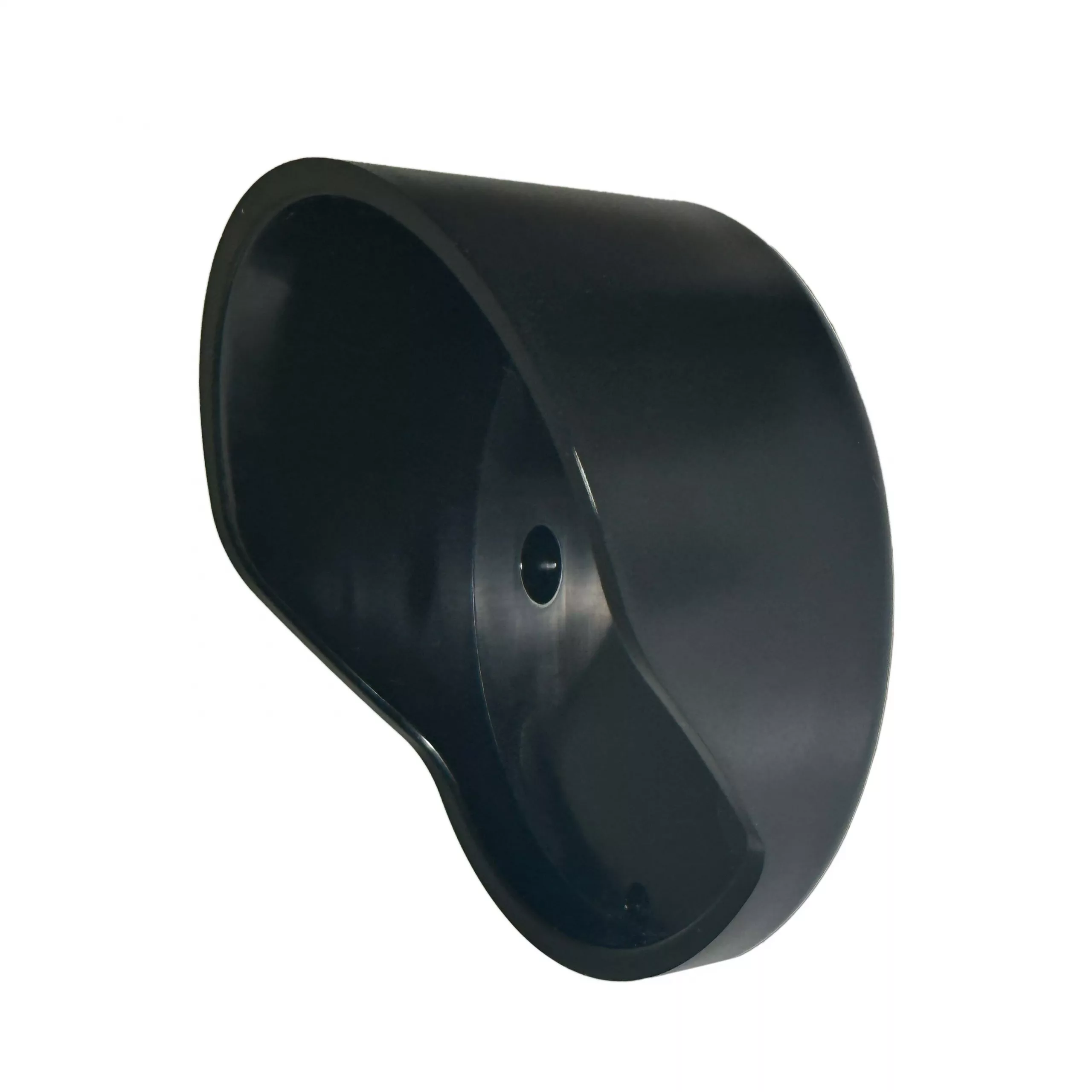
  • Integrated Sensor Hood
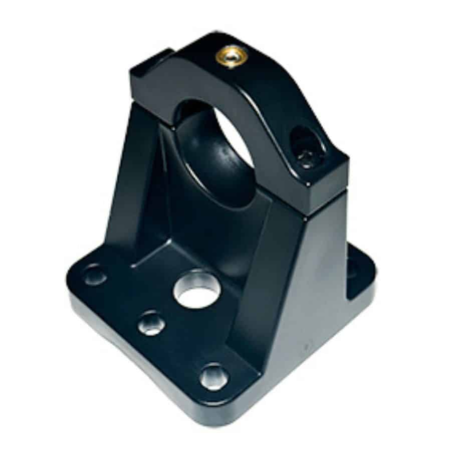
  • Ball and Socket Mounting Bracket
  • Selectable Stealth Mode

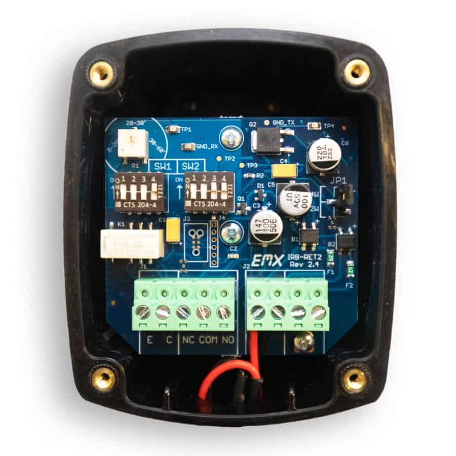
The IRB-RET2 universal UL325 retroreflective photoeye has 6 monitoring interfaces:

  • Normally closed
  • Two-wire pulse (2 freq)
  • Two-wire pulse (3 freq)
  • Four-wire pulse (2 freq)
  • Four-wire pulse (3 freq)
  • 10k resistive termination


IRB-RET2 RetroReflective Photoeye Specs

Operating range 5 ft (1.5 m) to 60 ft (18.3 m)
Sensitivity adjustment Potentiometer
Power 6-40 VDC, 12-24 VAC
Current (NC and 10K Monitoring Methods) 50 mA DC (relay activated)
Current (Pulse Monitoring Methods) 15 mA DC
Resistive Termination 10K ohm across NO contact (switch selectable)
Surge Protection Thermal fuse, MOV
Relay Output Operation Light ON/Dark ON
Response Time 250ms
Operating Temperature -30° to 140°F (-34° to 60°C)
Dimensions (L x W x H) 5.1” (130 mm) x 3.15” (80 mm) x 5.5” (140 mm)
Weight 0.7 lbs.
Ball Joint Mount Conduit Thread ½ Inch NPT

This universal UL325 retroreflective photoeye kit includes:

BALL AND SOCKET MOUNTING BRACKET
Easily mount on flat or curved surfaces

REFLECTOR-O-EX
White plastic reflector
3″ diameter

REFLECTOR-O-HD
Black plastic protective hood for reflector

STEEL MOUNTING BRACKET

Spec Sheet

Manual

How do I wire this photo eye to my operator?

Wiring Instructions: Follow the below table to identify the correct wiring diagram for your gate operator. Wiring diagrams are found in your EMX product manual. It will show the necessary wiring, dipswitch settings, and jumper settings. Check with your gate operator manual to make sure you are using the correct monitoring method associated with the diagram below. Updated as of 3/4/2025

Gate Operator EMX Diagram Monitoring Method
Apollo/Nice B 10K Resistive
All-O-Matic A Normally Closed
AutoGate B 10K Resistive
DoorKing B 10K Resistive
Eagle F 4 Wire Pulse (2 Frequency)
FAAC A Normally Closed
HySecurity A** Normally Closed
LiftMaster B 10K Resistive
Linear (apex) B 10K Resistive
Max Controls A or B NC or 10K
PowerMaster D* 2 Wire Pulse (2 Frequency)
US Automatic B 10K Resistive
Viking B 10K Resistive

Caution: * Using two wire pulse incorrectly can damage your device. Be advised to check your operator manual for proper wiring of your device.

Note: ** HySecurity gate operators using the SmartCNX Controller require 10K Resistive (Diagram B) or 4 Wire Pulse (Diagram F).

How do I configure my photo eye to be non-monitored?

Non-Monitored Setup: Follow diagram B, but the dipswitch SW2 position 1 should be off.

Why won’t my reflector align?

Sensitivity Adjustment: Set sensitivity to maximum by turning it clockwise until it stops. When the device aligns, turn the sensitivity back down as much as possible while the red light is still on solid.

Sensitivity Dial Image

DIP Switch Settings: Make sure the dipswitches at SW2 position 3 and 4 are fully on.

Transmitter Check: To make sure the transmitter is sending signal, look into the transmitter lens with your phone camera. You should see a crescent or circle of violet colored light.

Transmitter Check

My photo eye is hooked up to a power source but the green power light on the front of my photo eye is off.

DIP Switches: On the second set of dip switches labeled SW2, make sure switches 3 and 4 are in the on position. Those switches redirect power and only need to be in the off position for wiring Diagram C.

Check Power: Verify input power is between 6–40 VDC or 12–24 VAC with a multimeter.

Why does the red light on the front of my photo eye go on and off when I break the beam, but my gate doesn’t respond?

Monitoring Method Configuration: Make sure that the device is configured for the correct monitoring method for your gate operator. This can be found in your operator manual. Also common methods for various operators can be found in the above table under question, “How do I wire this device to my operator?” Then follow the corresponding diagram (A–F) found in the IRB-RET2 manual.

Why does my photo eye not detect an obstruction even though one is present?

Additional Reflection: Check area for highly reflective surfaces such as a shiny vehicle that may be sending the signal back to the receiver. Also wet ground may allow the signal to reflect under the vehicle. Try turning the sensitivity down, counterclockwise, until the device stops receiving a signal while an obstruction is present.

Sensitivity Dial Image

When my reflector is wet from rain or dew my photo eye will not align.

Reflector Maintenance: Apply a hydrophobic solution to the reflector. Like Rain-X: Plastic or a similar solution.

I changed my dipswitch settings but nothing happened.

Power Cycle: Remove power from the device for 15 seconds and then return power to it.

Why is my pulse output not working?

Jumper Position: Make sure the JP1 jumper is set to 2W for two wire pulse. For all other monitoring methods leave the jumper at 4W.

Jumper Position Image

Why is my relay not clicking when the infrared beam is blocked?

Dipswitch Settings: Make sure SW1 positions 1 and 2 are fully in the off position. These dip switches are only used to set 2 and 4 wire pulse modes which do not use the relay and so there will be no click when the beam is broken. If you meant to use these settings, then it is ok that the relay does not click.

Why does the red light on the front of my photo eye flash continuously?

Signal Issue: The IRB-RET2 is receiving a poor signal.

Adjust Alignment: The reflector may not be in the center of the infrared cone coming from the transmitter. To get the reflector to the center, hold the reflector in front of the IRB-RET2 at least 5 feet away. Then move the reflector in a circular motion to find the outer edges of the infrared cone where the red light begins flashing or turns off. Make sure the reflector is aligned at the center of this cone on installation.

Low Sensitivity: The sensitivity may be too low for the given distance. Increase the sensitivity by turning the dial clockwise until the red light goes on solid.

Sensitivity Dial Image

You may also like...

Have Any Questions ?

Have questions or need pricing on one of our products?