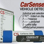
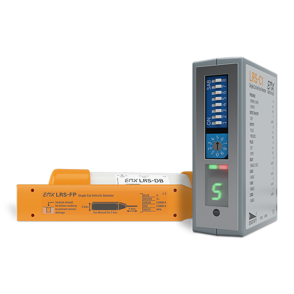
Product Overview for the LRS Vehicle Detector
It is no longer necessary to make 9 cuts to monitor vehicle presence…
The Loop Replacement System (LRS) features advanced 3-axis, magnetoresistive sensing technology that responds to changes in the Earth’s magnetic field caused by ferrous objects. Three sensing elements provide measurements in the X, Y and Z axes to improve detection sensitivity when used in either above or below ground installations.
The LRS is equipped with our new DETECT-ON-STOP™ or (DOS®) feature, which allows detection only when a vehicle has come to a complete stop. This EMX exclusive feature is a major advantage if you want to ignore cross traffic in tight spaces.
The detector’s compact, loop-less design reduces installation costs when compared to traditional inductive loop technology.
Features of Our Single Cut Vehicle Detector
The LRS system offers the following features:
- Three-dimensional presence detection of vehicles
- Select X, Y, Z axis independently
- Stand-alone sensor
- Sensor stores ambient background and settings in non-volatile memory
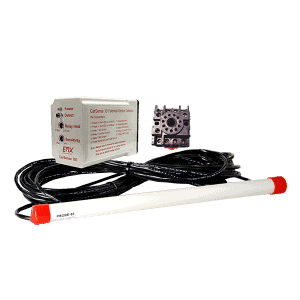
- Remote control module for programming and additional relay contact output
- ULTRAMETER™ displays optimum sensitivity setting/crosstalk interference
- DETECT-ON-STOP™ allows detection only when a vehicle has come to a complete stop
- Optional Logic Interface for extended detection
Loop Replacement System Specs
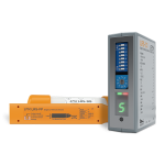
Control Unit
| Power/fault indicator | Green LED |
| Detect indicator | Red LED |
| Outputs | SPDT relay/NPN (open collector) |
| Output ratings | Relay: 1A @ 24VDC…120VAC NPN: 50 mA (max) |
| Connection | 10 position screw terminal |
| Housing | ABS |
| Environmental rating | IP30 |
| Power supply | 12-30 VDC and 24 VAC |
| Current draw | 40 mA max |
| Dimensions | 76mm (3.0”) x 22mm(0.9”) x 70mm(2.75”) |
| Weight | 68g (0.15 lbs.) |
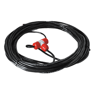
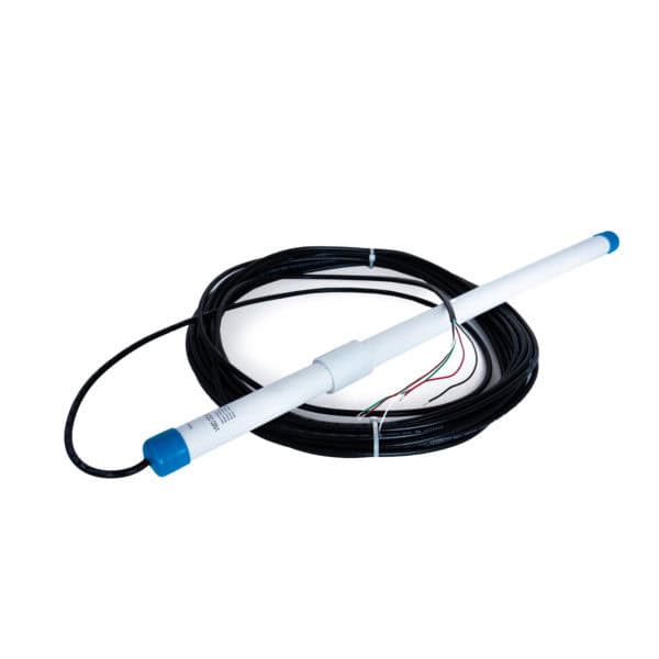
Sensor
| Outputs | NPN (open collector) |
| Output ratings | 50 mA |
| Connection | 5 conductor direct burial |
| Housing | DB: PVC; FP: Polyamide |
| Environmental rating | IP69K |
| Power supply | 12-30 VDC |
| Current draw | 10 mA max |
| Dimensions | DB:102mm (4.0”) x 27mm (1.0”); FP: 86mm (3.4”) x 21mm (0.9”) x 8mm (0.3”) |
| Weight | DB: 43g (0.09 lbs.); FP: 23g (0.05 lbs.) |
Control Unit & Sensor
| Sensing technology | 3-axis magnetoresistive |
| Sensitivity | 10 levels: 0-9 |
| Axis sensitivity | 512 counts/gauss (typical) |
| Environmental tracking | Automatic compensation |
| Local magnetic field nulling | Averages local field signature in any sensor orientation |
| Detection range | 1.5m (5ft.) |
| Pulse/presence | Allows the relay/NPN output to send either a pulse output or have constant presence |
| Detect-On-Stop | Requires vehicle to stop for a minimum of 1 second (1-2s typical) |
| Operating environment | -40°C…82°C (-40°F…180°F) |
| Supply protection circuitry | Reverse polarity and fuse protected |
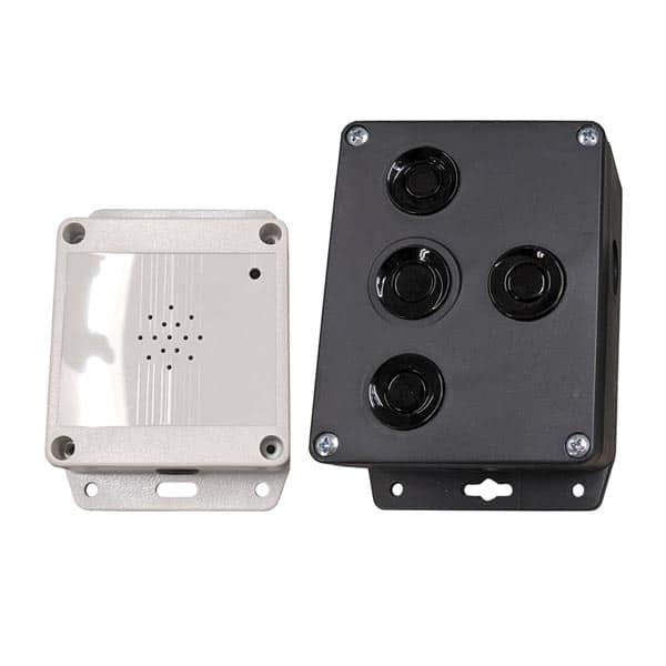
Logic Interface
| Power indicator | Green LED |
| Detect indicator | 2x Red LEDs |
| Configuration selector | 10 position rotary switch |
| Outputs | Relay 1: SPDT (form C) Relay 2: SPST (form A) |
| Output ratings | 1A @ 24 VDC/120 VAC |
| Operating environment | -40° C…82° C (-40° F…180° F) 0…95% relative humidity |
| Housing material | ABS |
| Enclosure | IP30 |
| Power | 12-30 VDC and 24 VAC |
| Operating current (standby/detect) | One sensor connected: 22/35mA Two sensors connected: 33/60mA |
| Supply protection circuitry | Reverse polarity and fuse protected |
| Dimensions | 73mm (2.9”) x 38mm (1.2”) x 78mm (3.1”) |
| Weight | 0.25 lbs. (113 g) |
| Connector | 11 pin male connector (JEDEC B11-88) |