PTM

Seven Day Programmable Timer

  • 16 events and 15 daily program combinations
  • 12, 24 or 120 Volt power supply option
  • Memory backup in case of power failure
  • DIN rail mount

PART NUMBERS:

  • EMX-5405-3: PTM-12 – 12 VDC/AC PROGRAMMABLE TIMER
  • EMX-5407-2: PTM-24 – 24 VDC/AC PROGRAMMABLE TIMER
  • EMX-5406-2: PTM-120 – 120 VAC PROGRAMMABLE TIMER

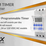
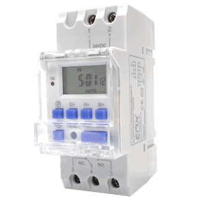
An Overview of Our PTM Timer

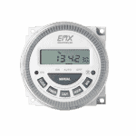
The PTM is an easy to program 7 day timer that provides secure access to any facility, any time. With up to 16 ON/OFF events per day and 15 different daily options, the PTM offers the best user flexibility. Its DIN rail mount design and wide power supply options (12, 24 or 120 Volt) make installation easy. The battery backup saves stored programs in the case of power loss. Select either a 12 or 24 hour clock format to program access times for overhead doors, gates and parking barriers. The PTM can reduce the wear and tear on motor controls and extend the life of your equipment.

Note: The PTM replaces our discontinued DTM-9 and ETM-17 timers. Please refer to our Timer Comparison Guide for more details.


Features of the PTM Programmable Timer

  • Flexible programming with 16 ON/OFF events per day
  • Large display and push-buttons for easy operation
  • Battery backup for power outages
  • DIN rail mount installation
  • Three power supply options


PTM Specs

Blackout Memory Protection90 days

Power & Current Draw 12 VDC/AC – 6 mA standby, 46 mA activated
24 VDC/AC – 15 mA standby, 37 mA activated
120 VAC – 33 mA standby and activated
Events 16 ON/OFF per day
Daily Program Options 15 combinations
Relay Contact Rating SPDT 16 A @ 24 VDC / 120 VAC
Operating Temperature 14°F to 122°F (-10°C to 50°C )
Surge Protection MOV protection devices
Blackout Memory Protection 90 days
Connections 5 screw terminals
Mounting DIN rail
Housing ABS plastic
Weight 0.2 lb (0.10 kg)
Dimensions (L x W x H) 3.41” (86.5 mm) x 1.42” (36 mm) x 2.70” (68.5 mm)

Spec Sheet

Manual

Timer Comparison Guide

Why is my PTM stuck always sending an output signal and the red light is always on?

Device ON: The device may be set to ON, which sends a constant output signal and does not change at scheduled event times. The PTM has three states. It can be either ON, AUTO, or OFF. The current state will be displayed in the bottom right corner of the device when looking at the current time. Pressing the Manual button will cycle the device between these states. Set to AUTO to use scheduled events.

Power Requirements: Make sure the PTM has the correct power. There are three different models of the PTM: PTM-12, PTM-24, and PTM-120. Each model of PTM must receive a voltage equal to the number in its name. Both AC and DC power are acceptable. Required power can also be found next to the power inputs, screw terminals 1(-) and 2. Power is polarity sensitive so if you are using DC power, make sure to connect the positive power leadwire to the positive terminal (2) and the negative power lead wire to the negative terminal (1).

PTM Relay

  1. While the PTM has power, disconnect any wires going into relay output contacts 3, 4, and 5 (NC, COM, NO) on your PTM.
  2. Set digital multimeter to check for continuity. On the PTM connect one meter lead to either screw terminal 3 (NO) or screw terminal 4 (NC), whichever is to be used. Connect the other meter lead to screw terminal 4 (COM).
  3. Press the manual button until the display reads OFF in the bottom right. The meter should read open (OL, INF) and should not beep yet. Press the manual button until the display reads ON. Verify the PTM red light turns on, and the meter reads less than 10 ohms and now beeps. If the meter is still showing open and does not beep, then the relay is defective.

Why is my PTM stuck never sending an output signal and the red light is always off?

Device OFF: The device may be set to OFF, which stops the device from sending an output signal and does not change at scheduled event times. The PTM has three states. It can be either ON, AUTO, or OFF. The current state will be displayed in the bottom right corner of the device when looking at the current time. Pressing the Manual button will cycle the device between these states. Set to AUTO to use scheduled events.

Power Requirements: Make sure the PTM has the correct power. There are three different models of the PTM: PTM-12, PTM-24, and PTM-120. Each model of PTM must receive a voltage equal to the number in its name. Both AC and DC power are acceptable. Required power can also be found next to the power inputs, screw terminals 1(-) and 2. Power is polarity sensitive so if you are using DC power, make sure to connect the positive power leadwire to the positive terminal (2) and the negative power lead wire to the negative terminal (1).

PTM Relay

  1. While the PTM has power, disconnect any wires going into relay output contacts 3, 4, and 5 (NC, COM, NO) on your PTM.
  2. Set digital multimeter to check for continuity. On the PTM, connect one meter lead to screw terminal 3 (NO) and the other meter lead to screw terminal 4 (COM).
  3. Press the manual button until the display reads OFF in the bottom right. The meter should read open (OL, INF) and should not beep yet. Press the manual button until the display reads ON. Verify the PTM red light turns on, and the meter reads less than 10 ohms and now beeps. If the meter is still showing open and does not beep, then the relay is defective.

How do I set the time?

Hold the clock button and press D+ to change the day, H+ the hour, and M+ the minute.

How do I set a schedule on my PTM timer?
  1. Press P to enter programming mode. Event 1 ON will be selected.
  2. Set the days using D+ to cycle through the different options. Set the hour with H+ and minute with M+.
  3. Press P again to select Event 1 OFF and repeat step 2.
  4. Continue through steps 1-3 until all events are set. Press the clock to get back to the current time.
  5. Make sure the PTM is set to AUTO to use the schedules that have been set. Press the manual button to cycle between ON, AUTO, and OFF.

How do I delete an event?

Events can be added and modified, but not removed. If an event needs removed, press the reset button to clear all events. Then add in desired events.

How do I test my PTM to make sure the schedule will actually work?
  1. Make sure the PTM is receiving proper power. Depending on which PTM timer you are using the input power will need to be 12VAC/DC, 24VAC/DC, or 120VAC.
  2. Set the device to ON. Press the manual button to cycle between ON, AUTO, and OFF. When set to ON the red ON light should turn on, the relay will activate making a click sound, and the gate should open.
  3. Once set to ON, press the manual button one time to change to AUTO. The red ON light should still be turned on once in AUTO.
  4. Set the current time on the clock to 1 minute before the PTM schedule is set to turn the device OFF. Hold the clock button and press H+ and M+ to change the current time.
  5. Wait 1 minute and when the clock hits the scheduled OFF time the red light will turn off and the gate will close.

You may also like...

Have Any Questions ?

Have questions or need pricing on one of our products?